All-Digital S-Band Telemetry Transmitter
MLXT-2250 series: up to 10 W from a GaN power stage, SOQPSK-TG and PCM/FM, every IRIG-106 LDPC code, RS-422/USB control and an AES-256 option. S-band standard, L- and C-band to 8 GHz on order. Flight-qualified for airborne, missile and UAV test.
Key specifications
| Model | MLXT-2250-100BW-20M |
|---|---|
| Frequency range | 2200–2300 MHz (S-band) L-, S- and C-band to 8 GHz, dual- and tri-band units on order |
| Occupied bandwidth | 100 MHz |
| Tuning step | Fine; defined at order to the program's channel plan |
| Modulation | SOQPSK-TG, PCM/FM ARTM CPM (multi-h), PCM/PM, OQPSK, STC, analog FM optional |
| Data rate | 500 kbps – 20 Mbps variants to 40 Mbps; below 500 kbps on request |
| Forward error correction | IRIG-106 LDPC, all six codes: K = 1024 and 4096, rates 1/2, 2/3, 4/5 IRIG randomizer, pre-modulation filtering, convolutional encoding for legacy receivers |
| RF output power | Options from 10 mW to 10 W higher power on request; programmable levels or commandable HIGH / LOW |
| Power amplifier | GaN |
| Data inputs | Clock and data, TTL or RS-422 LVDS, multiple inputs, UART, Ethernet / packetized data, automatic bit-rate detection optional |
| Control and status | RS-422 and USB, real-time parameter monitoring RS-232, Ethernet, CAN, MIL-STD-1553, discrete lines, pin-selected presets on request |
| Protection | Open/short load (VSWR), over-temperature, RF on/off command, inrush limiting |
| Input power | Isolated 18–36 VDC, reverse-polarity protected 12 V and 48 V inputs, low-power standby on request |
| Encryption | AES-256 option, or integration of a customer-furnished module |
| Connectors | SMA (RF), MDM (control) TNC or N, other MDM sizes, custom pinouts on request |
| Operating temperature | –40 °C to +80 °C base-plate |
| Environmental | Qualified for high vibration and acoustic loads MIL-STD-810 qualification programs on request |
| EMC | Key MIL-STD-461F requirements |
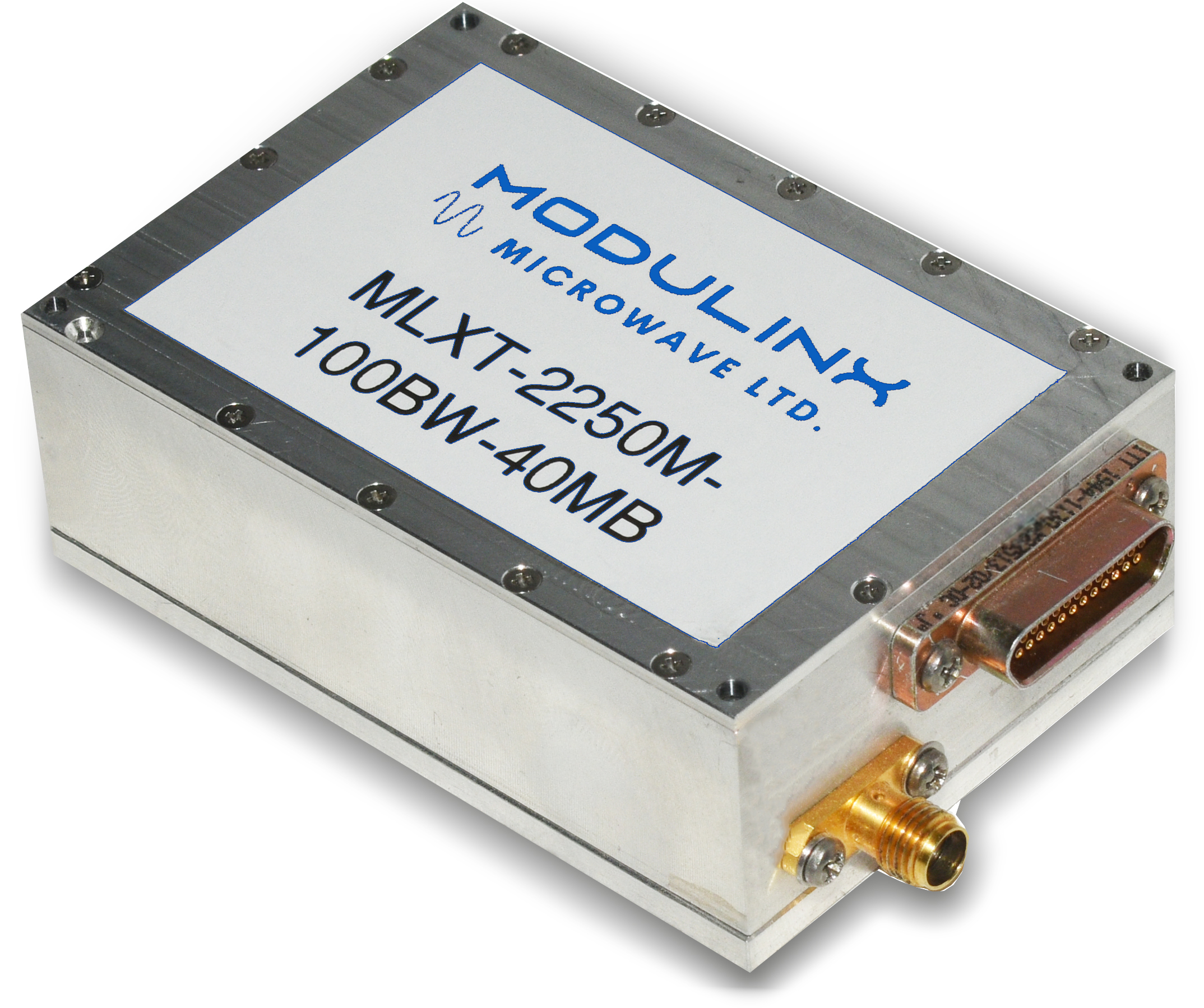
Standard configuration shown; optional items are described under Options and customization below. Full specifications, outline drawings and pin-outs are in the datasheet.
A flight-qualified S-band transmitter you configure in software
The MLXT-2250 is Modulinx Microwave's all-digital S-band telemetry transmitter for flight-test and defense programs. Covering 2200–2300 MHz with up to 10 W of RF output and 100 MHz of occupied bandwidth, it delivers a clean, spectrally efficient link with SOQPSK-TG or PCM/FM modulation. Integrated IRIG-106 LDPC forward error correction, all six codes, and a GaN power amplifier give the link the margin to hold through the harshest test environments.
Everything that used to require a different transmitter is now a setting or an ordered option: frequency, bit rate, FEC and power mode are configured over RS-422 or USB and can be changed during the mission; other bands up to 8 GHz, dual- and tri-band units, additional waveforms, digital video, AES-256 encryption, alternative data inputs and control buses are specified at order. The same interface returns status telemetry for real-time health monitoring.
Designed for airborne and rugged platforms, it operates from an isolated 18–36 VDC supply, is qualified for –40 °C to +80 °C at the base-plate and for high vibration and acoustic loads, and meets key MIL-STD-461F EMC requirements. Standard SMA RF and MDM control connectors make integration straightforward.
Up to 10 W from a GaN power stage, and more on request
Output power is specified at order, from 10 mW for short-range and captive-carry work up to 10 W for long-range links, with the same digital core and control interface across the range; higher power versions are available on request. The gallium nitride power amplifier delivers that power efficiently, so less of the vehicle's supply becomes heat on the base-plate, a decisive advantage on small airframes and sealed missile bays.
Output level is commandable: either as a dual power mode that switches between HIGH and LOW settings, LOW for ground checks, hangar testing and the early part of a mission, HIGH when range or link margin demands it, or as programmable output levels in steps. Either way the change is made over the control interface without touching the airframe, and the RF output can be switched on and off by command.
The output stage is protected against open and short loads (VSWR), so a disconnected or damaged antenna cable does not take the transmitter with it, and against over-temperature. Inrush current is limited at power-up to keep the vehicle bus clean.
SOQPSK-TG and PCM/FM, every IRIG-106 LDPC code, and more waveforms on order
The standard transmitter generates the two waveforms most flight-test ranges receive: PCM/FM, the IRIG-106 Tier 0 standard that every legacy ground station understands, and SOQPSK-TG, the Tier I waveform that fits the same data rate into roughly two-thirds of the bandwidth. With 100 MHz of occupied bandwidth available, a program can run high bit rates in SOQPSK-TG and still stay inside its frequency assignment. Data rates run from 500 kbps to 20 Mbps on the -20M model, up to 40 Mbps on other variants, and below 500 kbps on request.
Programs that need other waveforms can order them: ARTM CPM (multi-h CPM, the Tier II waveform for the most crowded spectrum), PCM/PM, OQPSK, space-time coding (STC) for two-antenna vehicles, analog FM for legacy video links, and an H.264 / H.265 digital-video option that carries compressed video over the telemetry link.
All six IRIG-106 LDPC codes are encoded in the transmitter: information block sizes of 1024 and 4096 bits at code rates 1/2, 2/3 and 4/5, so a program can trade bandwidth for margin per mission, from the most robust rate-1/2 code to the most efficient rate-4/5 code. The IRIG randomizer and pre-modulation filtering are built in, and convolutional encoding is available for ground stations that still decode it.
The coding gain shows up at the receiver as link margin, and the program decides how to spend it: more range, a smaller ground antenna, a lower power setting with less heat on the airframe, or a link that stays up through fades that would otherwise drop it. The Modulinx All-Digital Telemetry Receiver decodes the same codes and demodulates the same waveforms, for an end-to-end IRIG-106 link from one supplier.
Reconfigure it from the aircraft, even mid-mission
Data enters as clock and data on TTL or RS-422 as standard. LVDS inputs, several data inputs, a UART input, and Ethernet or packetized data input are available for instrumentation systems that speak something other than clock-and-data, and automatic bit-rate detection removes one more setting to get wrong before a flight.
A digital control interface over RS-422 and USB sets frequency, bit rate, FEC, modulation and power mode. Because the transmitter is all-digital, a frequency change for a new range or a bit-rate change for a new instrumentation load is a command, not a hardware variant, and it can be issued during the mission from the vehicle's data acquisition system. For integration into a specific vehicle, control over RS-232, Ethernet, CAN or MIL-STD-1553, discrete control lines, and preset configurations selected by connector pins are available on request.
The same interface reports the transmitter's main parameters in real time, so the flight-test engineer sees the health of the RF link alongside the rest of the vehicle's status, and an intuitive graphic user interface covers configuration on the bench.
Built for the airframe, not the bench
The transmitter runs from an isolated 18–36 VDC supply, so it tolerates the noisy, sagging bus of a test vehicle and does not couple ground loops into the instrumentation. Reverse-polarity protection covers the wiring mistake that ends a test day. Versions for 12 V and 48 V buses and a low-power standby mode for long-endurance vehicles are available on request.
It is qualified for base-plate temperatures from –40 °C to +80 °C and for the high vibration and acoustic loads of airborne and missile installations, and it meets the key MIL-STD-461F electromagnetic compatibility requirements, which means fewer surprises when the transmitter shares a bay with sensitive instrumentation. Programs that need formal MIL-STD-810 qualification, altitude, humidity, salt fog and the rest, a sealed or hermetic version, or base-plate temperatures beyond +80 °C can order a qualification program against their specification.
A compact outline with standard SMA RF and MDM control connectors keeps mechanical integration simple; TNC or N-type RF connectors, other MDM sizes, custom pinouts, custom mounting and a miniature version are available on request. Modulinx also builds the RF, power and control cable assemblies that connect the transmitter to the vehicle, to your drawings.
Options and customization
The MLXT-2250 is configured per program. Everything below is orderable; tell us what the vehicle needs and it becomes part of the quotation.
Bands and tuning
- L-band, S-band and C-band coverage, anywhere up to 8 GHz
- Dual-band and tri-band transmitters
- Tuning step defined to the program's channel plan
Power and protection
- Output power from 10 mW to 10 W; higher power versions
- Programmable output levels or commandable HIGH / LOW dual power mode
- 12 V and 48 V input versions, low-power standby mode
- Additional protection features to the program's specification
Waveforms, coding and video
- ARTM CPM (multi-h), PCM/PM, OQPSK, STC, analog FM
- H.264 / H.265 compressed digital video over the telemetry link
- Data rates below 500 kbps and variants up to 40 Mbps
- Convolutional encoding for legacy ground stations
Data inputs and control buses
- LVDS, multiple data inputs, UART, Ethernet / packetized data input
- Automatic bit-rate detection
- RS-232, Ethernet, CAN and MIL-STD-1553 control; discrete lines; pin-selected presets
Security and availability
- AES-256 encryption, or integration of a customer-furnished encryption module
- Dual-transmitter redundancy, developed to the program's requirement
- Frequency hopping, developed to the program's requirement
Mechanical and environmental
- TNC or N-type RF connectors, other MDM sizes, custom pinouts
- Custom mounting and outline, miniature version
- Sealed or hermetic construction, extended base-plate temperature
- MIL-STD-810 qualification programs against the program's environmental specification
Ordering the right configuration
The model designation encodes the configuration. MLXT-2250-100BW-20M, for example, is the S-band transmitter with 100 MHz of occupied bandwidth and a 20 Mbps maximum data rate. Band, output power, data rate, waveforms, FEC options, data inputs, control bus, encryption, connectors and environmental qualification are all specified at order.
Tell us the frequency assignment, data rate, required range, platform and the options you need, and we will propose a configuration and return a quotation with lead time.
Where the MLXT-2250 flies
Vehicles that need a robust telemetry link and a transmitter that adapts to the program.
Aircraft flight test
Fixed-wing and rotary-wing instrumentation with high data rates and a bus that is anything but clean.
Missiles and munitions
Sealed bays, extreme vibration and acoustic loads, and one chance to get the data down.
UAVs and targets
Small airframes where the efficiency of the GaN stage, the LOW power mode and the standby option keep heat and power budgets in check.
Sounding rockets and space launch
Short, violent flights that demand a transmitter qualified for the environment and a link with margin to spare.
Ground and sea trials
Vehicle, weapon and platform trials where the same transmitter moves between test articles as the program evolves.
Captive carry and lab integration
Bring the link up at 10 mW on the bench with the same unit that will fly, then switch to flight power.
Delivery, warranty and field support
Every transmitter is built to the ordered configuration. Typical lead time is about twelve months; the exact figure is stated in the quotation together with the configuration. The transmitter needs no periodic calibration, and the warranty runs two to three years depending on the contract.
Modulinx engineers come to the vehicle. Acceptance testing, integration into the airframe and participation in flight and field trials are available as paid services, in Israel and abroad, and we take part in any field test that involves our equipment.
Modulinx products are designed and manufactured in Israel and exported under Israeli Ministry of Defense export licensing. We supply customers in Israel, the United States and every other country approved by the Israeli authorities.
Telemetry transmitter FAQ
What does "all-digital" mean in a telemetry transmitter?
The waveform, FEC encoding and modulation are generated in digital logic and converted to RF, rather than built from analog modulator stages. Frequency, bit rate, modulation and FEC become settings, unit to unit performance is repeatable, and new capabilities arrive as firmware.
Which frequency bands does it cover?
The standard MLXT-2250 covers 2200–2300 MHz in S-band with 100 MHz of occupied bandwidth. L-band, S-band and C-band coverage anywhere up to 8 GHz can be ordered, as can dual-band and tri-band units, with the tuning step defined to your channel plan.
How much RF power does it produce?
Output power options range from 10 mW to 10 W from a GaN power amplifier, chosen at order, with higher power versions on request. Output is commandable, either as a HIGH / LOW dual power mode or as programmable levels in steps.
Which modulations and data rates are supported?
SOQPSK-TG and PCM/FM as standard. ARTM CPM (multi-h), PCM/PM, OQPSK, STC, analog FM and an H.264 / H.265 digital-video option can be ordered. The MLXT-2250-100BW-20M runs from 500 kbps to 20 Mbps; other variants reach 40 Mbps, and rates below 500 kbps are available on request.
Does it include forward error correction?
Yes. All six IRIG-106 LDPC codes (K = 1024 and 4096, rates 1/2, 2/3 and 4/5) are encoded in the transmitter, together with the IRIG randomizer and pre-modulation filtering; convolutional encoding is available for legacy ground stations. Any IRIG-106 LDPC receiver decodes the link, including the Modulinx All-Digital Telemetry Receiver.
Can settings be changed in flight?
Yes. Frequency, bit rate, FEC, modulation and power mode are set over RS-422 or USB and can be changed during the mission, and the same interface returns real-time status of the main parameters. Control over RS-232, Ethernet, CAN or MIL-STD-1553, discrete lines and pin-selected presets are available on request.
Is encryption available?
Yes. AES-256 encryption is available as an option, or Modulinx integrates a customer-furnished encryption module. Frequency hopping and dual-transmitter redundancy are developed to a program's specific requirement.
What power supply and environment does it need?
An isolated 18–36 VDC input with reverse-polarity protection; 12 V and 48 V versions and a low-power standby mode are available. The transmitter is qualified for –40 °C to +80 °C at the base-plate, for high vibration and acoustic loads, and for key MIL-STD-461F EMC requirements; MIL-STD-810 qualification programs, sealed versions and extended temperature are ordered against your specification.
Can the connectors and outline be changed?
Yes. SMA RF and MDM control connectors are standard; TNC or N-type RF connectors, other MDM sizes, custom pinouts, custom mounting and a miniature version are available on request.
What are the lead time and warranty?
Typical lead time is about twelve months, stated precisely in the quotation. Warranty is two to three years depending on the contract, and the transmitter needs no periodic calibration. Field support by Modulinx engineers, in Israel or abroad, is available as a paid service.
Can you export to my country?
Modulinx exports under Israeli Ministry of Defense export licensing and supplies customers in Israel, the United States and every other country approved by the Israeli authorities. Tell us where the equipment will be used and we will confirm before quoting.
How do I get the datasheet or a quotation?
Use the Download datasheet button on this page for the full specification and outline drawing, or send us your frequency assignment, data rate, range, platform and options through the contact page for a configuration and quotation.
Complete the link
All-Digital Telemetry Receiver
Two receivers and a pre-detection diversity combiner in a 3U or 1U chassis or a rugged field case. PCM/FM, SOQPSK-TG and BPSK to 28 Mbps, all six IRIG-106 LDPC codes, S-band with L- and C-band to 8 GHz on order.
See the receiverCable assemblies and wire harnesses
Build-to-print RF, power and control harnesses for the transmitter installation, made under an AS9100-aligned workflow from prototype to production.
See cable assembliesSpecifying a transmitter for your vehicle?
Send us the frequency assignment, data rate, range, platform and options. We will propose a configuration and a quotation.